 CanHobby.ca
The CanHobby ATTiny10-LED is a minimal development board for the ATtiny10 MCU from MicroChip. It is designed to be used on a breadboard and has a single on-board LED connected to B1. It should be noted that later revisions of the ATTiny10-LED board have a solderpad on the bottom to enable the LED.
Everyone knows how to write an Arduino blink sketch but the ATTiny10 is a little different. Due to it's limited (could I say non-existent RAM) and Flash memory, conventions such as digitalWrite() do not exist. This sketch will illustrate the use of "Register Programming" which is at a lower level, just one step above assembler.
The Boards Package used in this example is ATtinycore10 from Technoblogy. The Boards Manager URL to add to the Arduino IDE preferences dialog is:
http://www.technoblogy.com/package_technoblogy_index.json
I am actually including 3 different methods to blink the LED.
- "Normal" - Write High - delay - Write Low Loop
- Using the "Toggle" feature available on limited AVR MCUs.
- Using the Timer with Output Compare GPIO.
- Using Timer interrupts to make a "heartbeat" dimmer.
"Normal" method
#include <util/delay.h>
#define B1 2
void setup() {
DDRB |= B1; // Set bit #1 to 1 to enable GPIO1 as OutPut
}
void loop() {
PORTB |= B1; // Set GPIO1 to HIGH
_delay_ms( 1000 ); // wait for 1000 mSec
PORTB &= ~B1; // Set GPIO1 to LOW
_delay_ms( 1000 ); // wait for 1000 mSec
}
Toggle Method
This method takes advantage of a feature found on a limited set of AVR MCUs such as the ATmega328 (it may be used on an UNO or Nano), the ATTiny85 and the ATTiny10. Setting a bit to 1 in the InPut register will cause the corresponding GPIO pin to Toggle state. We save 2 lines of code using this method. Here is the modified loop() function:
void loop() {
        PINB |= B1;        //  Toggle GPIO1
       _delay_ms( 1000 );  //  wait for 1000 mSec
}
Timer Method
We can initialize the timer to run continuously and toggle B1 every 1000 mSec in the setup() function. The loop function is only there to keep the Arduino IDE happy. This method has the advantage of not using any execution resources. We could put some code in the loop and it would not be affected by the blinking, as if the LED was being operated in the background.
// Let the compiler do the hard work

#if (F_CPU/1000000)<5  //  For SYS_CLK < 5 MHz
  #define COMPARE    F_CPU / 64  // Value to load into OutPut Compare A Register
  #define PRE_SCALE  3           // PreScaler option = / 64
#else                  //  For SYS_CLK >= 5 MHz
  #define COMPARE    F_CPU / 256  // Value to load into OutPut Compare A Register
  #define PRE_SCALE  4            // PreScaler option = / 256
#endif

#define B1 2    //  LED is on GPIO B1
void setup () {
  DDRB = B1;    //  Set LED pin to OutPut

  TCCR0A = 1<<COM0B0 | 0<<WGM00;  // Toggle OC0B = GPIO B1 using CTC mode

  TCCR0B = 1<<WGM02 | PRE_SCALE<<CS00;  // CTC mode using OCR0A;

  OCR0A    = COMPARE;  //  ( F_CPU / 64 );  // = 15624 --  1 second  ie 0.5Hz

}

void loop () {}  //  just to keep the IDE happy.
Timer with Interruputs - PWM mode
Here we use an interrupt on every compare match to change the PWM Pulse Width to create a repetitive min to max brightness sequence for a "heartbeat" effect.
Defines and ISR routines.
#include <util/delay.h>

// Let the compiler do the hard work

#if (F_CPU/1000000)<5  //  For SYS_CLK < 5 MHz
  #define COMPARE    F_CPU / 64  // Value to load into OutPut Compare A Register
  #define PRE_SCALE  1           // PreScaler option = / 64
#else                  //  For SYS_CLK >= 5 MHz
  #define COMPARE    F_CPU / 256  // Value to load into OutPut Compare A Register
  #define PRE_SCALE  2            // PreScaler option = / 256
#endif

#define B1 2

#define INVERT_mode    2
#define nonINVERT_mode 3

#define OVF_irq   1 // Enable OverFlow IRQ
#define COMPA_irq 2 // Enable CMPA IRQ
#define COMPB_irq 4 // Enable CMPB IRQ

ISR( TIM0_COMPB_vect ) {  //  We will change the OCR0B value in increments of 128 (80HEX)
  if( OCR0B > 0x82 ) { OCR0B -= 0x80; } else { OCR0B = 0x3F80; }
}
setup()...
Read more »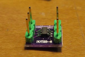
 kodera2t
 mihai.cuciuc
 Jens Hauke
 Yann Guidon / YGDES